The four forces of flight
Understand lift, weight, thrust and drag, then see why balanced forces allow steady flight and why lift can be less than weight in a climb.
The four forces of flight are lift, weight, thrust and drag. Their size and direction determine whether an aeroplane accelerates. Balanced forces mean zero acceleration, so an aircraft can keep moving while the forces balance. 1.
The familiar “lift equals weight, thrust equals drag” diagram describes a simplified straight-and-level case. In a climb or turn, check the force directions before using those equalities.
What direction does each force act in?
Start with directions. A force has both a magnitude and a direction; adding forces means combining both. An arrow representing a force is called a vector.
| Force | Direction | Reference to keep in mind |
|---|---|---|
| Lift, L | Perpendicular to the undisturbed relative airflow | It is not necessarily vertical |
| Weight, W | Vertically down, towards the Earth’s centre | It does not tilt with the aircraft |
| Thrust, T | Along the propulsion system’s thrust line | That line need not coincide with the flight path |
| Drag, D | Parallel to the relative airflow, opposing motion through the air | It is not necessarily horizontal |
Lift and drag are components of the aerodynamic force. Here, relative airflow means the oncoming air as seen by the aircraft, before the aircraft disturbs it. It is opposite the aircraft’s motion through that air. 1, 2.
We use a whole-aircraft force model. The lift label represents the combined lift contribution, including the tail’s contribution, rather than the wing alone. Forces acting at different points can also create turning effects called moments. Steady attitude requires those moments to balance too; the diagrams below examine only the overall force balance. 1.
Balanced forces allow steady motion
Assume straight-and-level flight at constant speed, with thrust and drag horizontal and lift vertical. Then:
L = W and T = D
Each pair cancels. There is no remaining force to change the aircraft’s velocity. That does not stop the aircraft: its speed and direction remain constant. Newton’s laws concern changes in motion, not a requirement for a forward force simply because something is moving. 1.
Suppose, in an original teaching example, lift and weight are each 10 kN, while thrust and drag are each 2 kN. A kilonewton (kN) is 1,000 newtons, a unit of force. Both pairs balance, even though the vertical forces are much larger than the horizontal forces.
“All four forces balance” does not mean all four have the same magnitude.
A steady climb can have lift less than weight
Climbing does not, by itself, mean accelerating. Once the aircraft follows a straight upward path at constant speed, its velocity is constant and the net force is zero. 2.
For the climb model below, assume still air, wings level, no sideslip, constant speed and a straight flight path. Assume thrust acts along that path. Let γ (gamma) be the flight-path angle above the horizontal.
Resolve weight into two components:
- W sin γ acts backwards along the path, adding to the force thrust must overcome.
- W cos γ acts perpendicular to the path, opposite lift.
The balance becomes:
T = D + W sin γ
L = W cos γ
For a positive climb angle, thrust exceeds drag and lift is less than weight in this model. These are the straight steady climb relationships set out in EASA’s flight-mechanics learning material. 3.
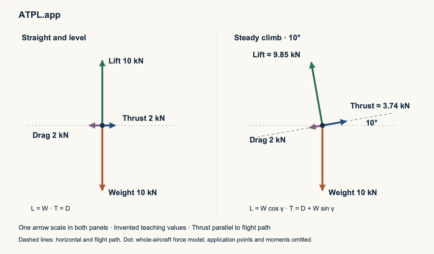
Original force diagrams using one scale. The dots represent the aircraft as a whole, not the actual points where each force acts. Thrust is assumed parallel to the flight path.
For a hypothetical 10° climb, take weight as 10 kN and drag as 2 kN:
- Lift = 10 × cos 10° ≈ 9.85 kN.
- Thrust = 2 + 10 × sin 10° ≈ 3.74 kN.
These invented values illustrate the equations; they are not performance data for an aircraft. Although thrust exceeds drag, the rearward component of weight accounts for the difference. No net force remains along the path to increase speed. UK CAA’s aircraft-motion model likewise includes both acceleration and the component of weight along an inclined path. 4.
During the transition into a climb, the flight path changes. The steady-climb equations do not describe that pull-up.
A glide needs no propulsive thrust to continue moving
In an idealised straight, steady glide with zero thrust, weight has a component along the descending path that balances drag. The component perpendicular to the path balances lift. The aeroplane loses height while maintaining speed. 3.
Energy explains how this can continue: height provides gravitational potential energy, which is spent overcoming drag. The ICAO and aircraft-manufacturer training aid describes this exchange between altitude, speed and propulsive energy. 5.
The forward component comes from weight, not an engine. Keep that distinction when labelling a glide diagram.
Constant speed in a turn still involves acceleration
Speed is only the magnitude of velocity. Velocity also includes direction. An aircraft turning at constant speed changes its velocity because its direction changes.
In a simplified coordinated level turn, neglect any thrust component perpendicular to the flight path. Bank tilts lift. Its vertical component supports weight; its horizontal component provides the inward force that curves the path. The net force is therefore not zero, even when speed and altitude stay constant. 1.
When reading a force diagram, check both speed and direction before deciding whether the forces should balance.
Check your understanding
For each statement, decide whether it follows from the models above:
- An aircraft moving at constant speed along a straight, level path needs thrust greater than drag.
- In the steady-climb model, thrust greater than drag proves that the aircraft must be accelerating.
- An aircraft turning at constant speed has zero acceleration.
All three are false. In the first case, thrust balances drag. In the second, thrust also balances the component of weight along the climbing path. In the third, changing direction is acceleration, even without a change in speed.
References
-
UK Ministry of Defence, AP3456, Volume 1: The Principles of Flight: chapter 1-2, paragraphs 19–21 (lift, drag and free-stream flow); chapter 1-13, paragraphs 1–3 (level-flight forces and moments); chapter 1-15, paragraph 7 and paragraphs 30–32 (Newton’s laws and turning).
-
NASA Glenn Research Center, Forces in a Climb: force directions, thrust-alignment assumption and component equations.
-
EASA, Annex II to ED Decision 2016/008/R: subject 081, straight steady climb and glide, pp. 500–501. Used for stable theoretical relationships, not a claim about current licensing requirements.
-
UK CAA-hosted R&D Report 9842, ANCON: Improvements in Version 2, June 1999: section 4.4–4.5, pp. 6–7. Historical NATS research prepared for the UK Department of the Environment, Transport and the Regions; used for its stated force model, not as operational guidance.
-
ICAO and aircraft manufacturers, Airplane Upset Prevention and Recovery Training Aid, revision 3, February 2017: sections 6.1–6.2, flight dynamics and energy states. Used for the energy explanation, not recovery procedures.